In this project, we will see how to Connect I2C LCD with Arduino. We have already seen how to interface a regular 16×2 LCD with Arduino. By using an I2C LCD with Arduino, you can preserve all the digital I/O Pins of Arduino UNO and work with LCD using I2C Communication.
Introduction
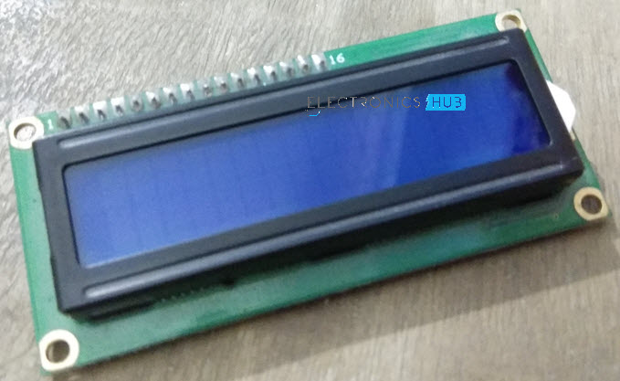
An alphanumeric character LCD like the one shown in the following image is one of the frequently used components in many DIY projects. It is often used with Arduino to display a wide range of information like sensor readings, messages from GSM Module, or any status information.
The simplest way to connected a 16×2 or 20×4 character LCD is to select a required sized LCD module and connect it Arduino UNO in a 4-bit mode. But the main drawback of this setup is that even in 4-bit mode, the LCD needs 6 digital IO pins of Arduino for proper communication.
If your project needs to interface with several sensors and other IO devices then you will probably need as many IO pins from Arduino as possible. If the LCD itself utilizes 6 of the available 13 digital IO pins, then you are left with just 7 pins for interfacing other components.
How to Connect I2C LCD with Arduino?
The solution to this is to use an I2C LCD with Arduino. For this, an I2C based GPIO expander is used with a regular 16×2 Alphanumeric Character LCD.
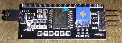
The following image shows a module based on PCF8574 IC which is configured specifically for LCD Displays.
You can plug-in this module directly to the pins of the regular LCD and using I2C communication with Arduino (or any microcontroller) you can transmit the data.
A Brief Note on PCF8574
PCF8574 is an I2C based I/O expander IC that provides 8-bit I/O expansion for microcontrollers with I2C interface. Using just two lines of the I2C Interface i.e. the SDA (Serial Data) and SCL (Serial Clock), you can configure 8 bidirectional I/O Pins.
NOTE: A separate tutorial on PCF8574 GPIO Extender will be presented. So, I will provide more detailed information on the PCF8574 IC in that tutorial.
Circuit Diagram of I2C LCD with Arduino
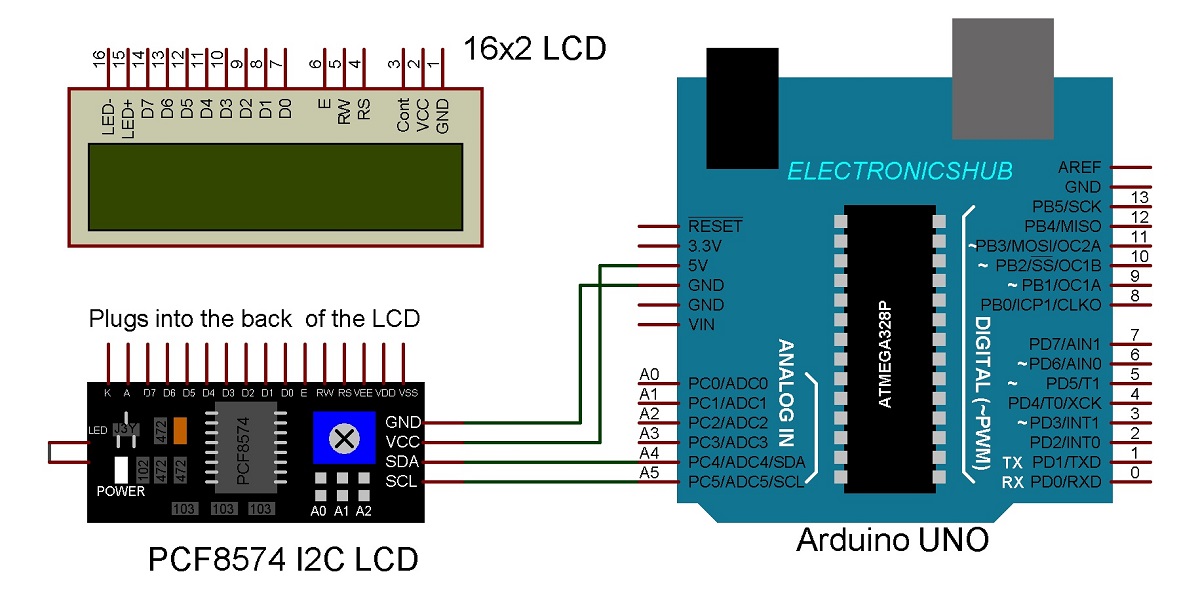
The circuit diagram for connecting I2C LCD with Arduino is shown in the following image.
Components Required
- Arduino UNO
- 16×2 LCD Display
- PCF8574 I2C LCD Backpack
- Connecting Wires
Circuit Connections
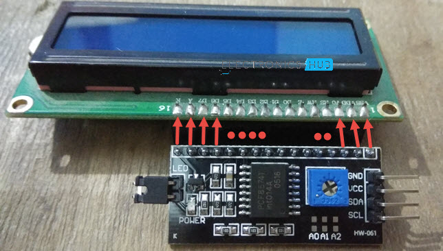
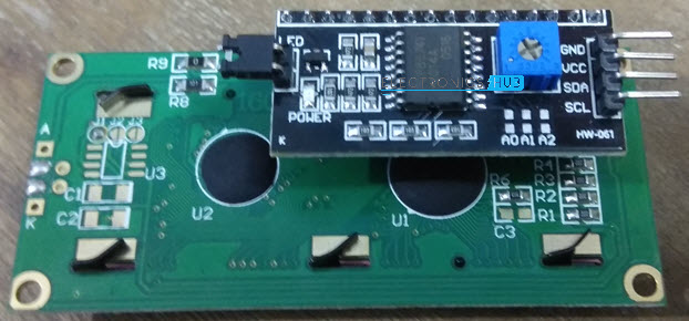
First, plug-in the PCF8574 Module on the back of the LCD Display. Check the pins of both the modules. Use the following image as a reference.
Usually, the I2C Pins come out of the LCD Module for easy connection with Arduino as shown in the following image.
After connecting the I2C Module to LCD, connect the GND and VCC pins of the PCF8574 Module to GND and 5V pins of Arduino. Finally, the SDA and SCL Pins. Connect them to pins A4 and A5 pins of Arduino UNO respectively.
Code
Code for I2C Slave Address
An important step in I2C Communication is figuring out the address of the slave device. Based on the A0, A1 and A2 pins of the PCF8574 IC, the address of the I2C Slave module is fixed.
Instead of calculating the slave address from the datasheet, let us use a simple code for Arduino to determine the address and display it to us on the serial terminal. First of all, make the connections as per the above circuit diagram.
Then upload the following code to view the I2C Slave address.
#include
void setup()
{
Wire.begin();
Serial.begin(9600);
while (!Serial);
}
void loop()
{
byte error, address;
int I2CDevices;
Serial.println(“Scanning for I2C Devices…”);
I2CDevices = 0;
for (address = 1; address < 127; address++ )
{
Wire.beginTransmission(address);
error = Wire.endTransmission();
if (error == 0)
{
Serial.print(“I2C device found at address 0x”);
if (address < 16)
Serial.print(“0”);
Serial.print(address, HEX);
Serial.println(” !”);
I2CDevices++;
}
else if (error == 4)
{
Serial.print(“Unknown error at address 0x”);
if (address < 16)
Serial.print(“0”);
Serial.println(address, HEX);
}
}
if (I2CDevices == 0)
Serial.println(“No I2C devices found\n”);
else
Serial.println(“****\n”);
delay(5000);
}
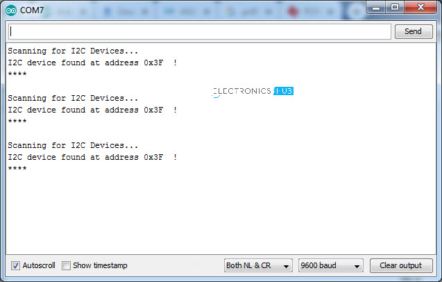
After uploading the code, open the serial monitor and set the baud rate to 9600. In my case, the address is 0X3F. So, in the actual programming (to display stuff on the LCD), I have to use this address.
Code for Displaying on LCD
Before going into the code, you need a special library called “LiquidCrystal_I2C”. It is based on the “LiquidCrystal” library we normally use but modified for I2C communication. You can download the library from this link.
Download the zip file, extract the contents and rename the directory to “LiquidCrystal-I2C” and place the folder in the libraries of your Arduino installation (usually, C:\Program Files (x86)\Arduino\libraries).
The following is a simple test code for displaying text on the LCD Module.
#include
#include
// Set the LCD address to 0x3F for a 16 chars and 2 line display
LiquidCrystal_I2C lcd(0x3F, 16, 2);
void setup()
{
lcd.begin();
lcd.backlight();
lcd.setCursor(0,0);
lcd.print(” I2C LCD with “);
lcd.setCursor(0,1);
lcd.print(” ARDUINO “);
}
void loop()
{
// Do nothing here…
}
Working
The working of the project is very simple. It is simply an I2C Protocol with an extension of LCD Display. Since the slave addresses on I2C Bus are important, be very careful in calculating them, as they are directly used in the program. Apart from the I2C Slave Address, all the other function of LCD are similar to a regular LCD Library.
Applications
- By using an I2C based LCD, the number of Digital IO pins required to communicate with an LCD will become zero. This will be helpful in connecting other sensors and actuators to the microcontroller (Arduino, in this case).
- Since the communication used is I2C, you can connect up to 8 similar LCD displays on the same I2C Bus. This is possible by modifying the Address pins of the PCF8574 IC for each LCD.
The post How to Connect PCF8574 I2C LCD with Arduino? appeared first on Electronics Hub.
0 Comments