In this tutorial, we will learn about Schmitt Trigger, some basic implementations using Transistors, Op-Amp, how a Schmitt Trigger works and few important applications as well. In an earlier tutorial, we have seen How 555 Timer can be configured as Schmitt Trigger.
Introduction
When operating an Op-Amp in the open loop mode where a feedback is not used, for example, in a Basic Comparator Circuit, the very large open loop gain of the Op-Amp will cause the smallest of noise voltage to trigger the comparator.
If the comparator is being used as a Zero Crossing Detector, then such false triggering can cause a lot of problems. It may give a wrong indication of Zero Crossing due to zero crossing of the noise rather than the actual input signals’ zero crossing.
To avoid such unnecessary switching between high and low states of the output, a special circuit called Schmitt Trigger is used, which involves a positive feedback.
What is Schmitt Trigger?
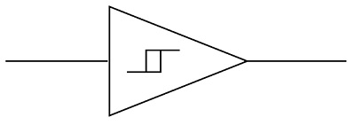
Schmitt Trigger was invented by Otto Schmitt early 1930’s. It is an electronic circuit that adds hysteresis to the input-output transition threshold with the help of positive feedback. Hysteresis here means it provides two different threshold voltage levels for rising and falling edge.
Essentially, a Schmitt Trigger is a Bi-stable Multivibrator and its output remains in either of the stable states indefinitely. For the output to change from one stable state to other, the input signal must change (or trigger) appropriately.
This Bistable operation of the Schmitt Trigger requires an amplifier with positive feedback (or regenerative feedback) with a loop gin greater than one. Hence, Schmitt Trigger is also known as Regenerative Comparator.
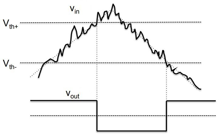
For example, if we have a noisy input signal as shown below, the two thresholds of the Schmitt Trigger Circuit will correctly determine the pulses. Hence, the basic function of a Schmitt Trigger is to convert noisy square, sine, triangular or any periodic signals into clean square pulses with sharp leading and trailing edges.
Schmitt Trigger using Transistors
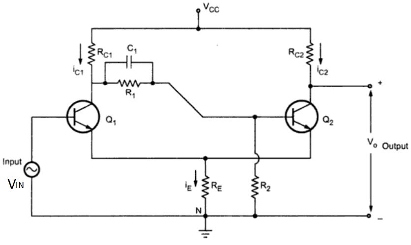
As mentioned earlier, a Schmitt Trigger is basically a Bistable Circuit whose output states are controlled by the input signal. Hence, it can be used as a level detecting circuit. The following circuit shows a simple design of Transistor based Schmitt Trigger.
Even though this circuit looks like a typical Bistable Multivibrator circuit, it is actually different as this circuit is missing the coupling from collector of Q2 to input of Q1. Emitters of Q1 and Q2 are connected to each other and grounded through RE. Also, RE acts as a feedback path.
Operation of the Circuit
When VIN is zero, Q1 is cut-off and Q2 is in saturation. As a result, the output voltage VO is LOW. If VCE(SAT) is assumed to be 0, then the voltage across RE is given by:
(VCC x RE) / (RE + RC2)
This voltage is also the emitter voltage of Q1. So, for Q1 to conduct, the input voltage VIN must greater than sum of the emitter voltage and 0.7 V i.e.
VIN = (VCC x RE) / (RE + RC2) + 0.7
When the VIN is greater than this voltage, Q1 starts conducting and Q2 is cutoff due to regenerative action. As a result, the output VO goes HIGH. Now the voltage across the RE changes to a new value and is given by:
(VCC x RE) / (RE + RC1)
Transistor Q1 will conduct as long as the input voltage VIN is greater than or equal to the following:
VIN = (VCC x RE) / (RE + RC1) + 0.7
If VIN falls below this value, then Q1 comes out of saturation and the rest of the circuit operates is due to regenerative action of Q1 going to cutoff and Q2 to saturation.
The output states HIGH and LOW are dependent on the input voltage levels given by the equations
(VCC x RE) / (RE + RC1) + 0.7 and (VCC x RE) / (RE + RC2) + 0.7
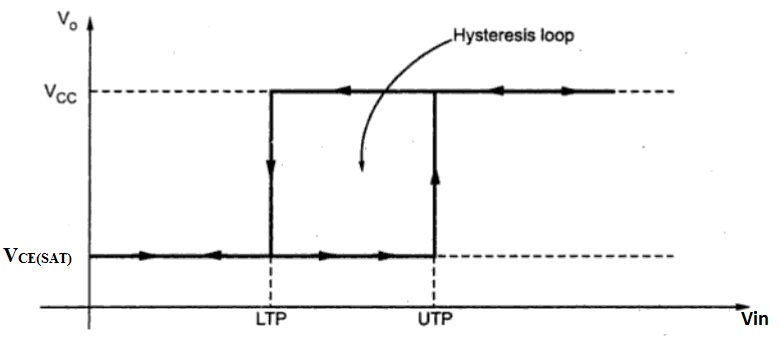
The transfer characteristics of a Schmitt Trigger exhibit hysteresis and are governed by the Lower Trip point (Lower Threshold Voltage) and Upper Trip point (Upper Threshold Voltage) given by VLT and VUT.
VLT = (VCC x RE) / (RE + RC1) + 0.7
VUT = (VCC x RE) / (RE + RC2) + 0.7
By changing the values of RC1 and RC2, the amount of hysteresis can be controlled while the value of RE can be used to increase the Upper Threshold Voltage.
Op Amp based Schmitt Trigger Circuits
Since a Schmitt trigger circuit is essentially an amplifier with positive feedback, it is possible to implement this setup using operational amplifiers or simply Op Amps. Depending on where the input is applied, the Op-Amp based circuits can be further divided into Inverting and Non-Inverting Schmitt Triggers.
Inverting Schmitt Trigger Circuit
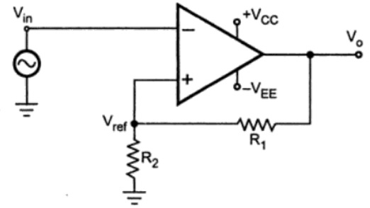
As the name suggests, in an Inverting Schmitt Trigger, the input is applied to the inverting terminal of the Op-Amp. In this mode, the output produced is of opposite polarity. This output is applied to non-inverting terminal to ensure positive feedback.
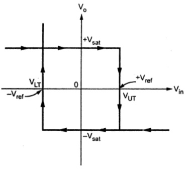
When VIN is slightly greater than VREF, the output becomes -VSAT and if VIN is slightly less that -VREF (more negative than -VREF), then output becomes VSAT. Hence, the output voltage VO is either at VSAT or -VSAT and the input voltage at which these state changes occur can be controlled using R1 and R2.
The values of VREF and -VREF can be formulated as follows:
VREF = (VO x R2) / (R1 + R2), VO = VSAT. Hence, VREF = (VSAT x R2) / (R1 + R2)
-VREF = (VO x R2) / (R1 + R2), VO = -VSAT. Hence, -VREF = (-VSAT x R2) / (R1 + R2)
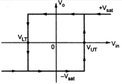
The reference voltage VREF and -VREF are called Upper Threshold Voltage VUT and Lower Threshold Voltage VLT. The following image shows the output voltage versus input voltage graph also known as the Transfer Characteristic of Schmitt Trigger.
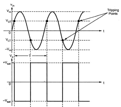
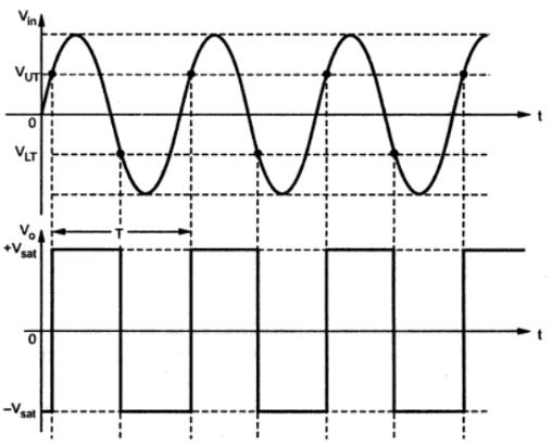
For a pure sinusoidal input signal, the output of an Inverting Schmitt Trigger Circuit is shown in the following image.
Non-Inverting Schmitt Trigger Circuit
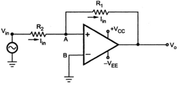
Coming to Non-Inverting Schmitt Trigger, the input in this case is applied to the non-inverting terminal of the Op-Amp. The output voltage is fed back to the non-inverting terminal through the resistor R1.
Let us assume that initially, the output voltage is at VSAT. Until VIN becomes less than VLT, the output stays at this saturation level. Once the input voltage crosses the lower threshold voltage level, the output changes state to -VSAT.
The output remains at this state until the input rises beyond the upper threshold voltage.
Following image shows the transfer characteristics of non-inverting Schmitt Trigger circuit.
If a pure sinusoidal signal is applied as input, then the output signals looks something like this.
Applications
- One important application of Schmitt Trigger is to convert Sine waves into Square waves.
- They can be used to eliminate chatter in Comparators (a phenomenon where multiple output transitions are produced due to swinging of input signal through the threshold region).
- They can also act as simple ON / OFF Controllers (for example, temperature based switches).
The post Schmitt Trigger Basics | How Schmitt Trigger Works? appeared first on Electronics Hub.
0 Comments