In the previous tutorials we have seen about Low Pass and High Pass Filters. In this tutorial, we will learn about another category of filters known as Band Pass Filters. In particular, we will learn about Passive Band Pass RC Filter, its basic circuit, functionality, frequency response, applications and many more.
For more information on Low Pass or High Pass filters, read the tutorials on Passive High Pass RC Filters, Passive Low Pass RC Filters, Active High Pass Filter and Active Low Pass Filter.
Introduction
We can say that a Band pass filter is a combination of both low pass filter and high pass filter. The name of the filter itself indicates that it allows only a certain band of frequencies and blocks all the remaining frequencies.
In audio applications, sometimes it is necessary to pass only a certain range of frequencies, this frequency range do not start at 0Hz or doesn’t end at very high frequency but these frequencies are within a certain range, either wide or narrow. These bands of frequencies are commonly termed as Bandwidth.

Passive Band Pass filter
Band pass filter is obtained by cascading passive low pass and passive high pass filters. This arrangement will provide a selective filter which passes only certain frequencies. This new RC filter circuit can able to pass either a narrow range of frequencies or wide range of frequencies.
This passage range of frequencies that is either narrow or wide range will depend upon the way the passive low pass and high pass filter cascade. The upper and lower cut-off frequencies depend on filter design. This band pass filter is simply appears like a frequency selective filter.
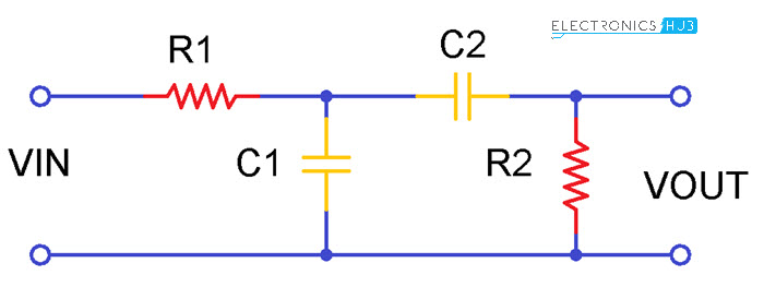
The above figure shows the Band pass filter circuit. The input given is a sinusoidal signal. The properties of low pass and high pass combinations give us Band pass filter. By arranging one set of RC elements in series and another set of RC elements in parallel the circuit behaves like a band pass filter.
This gives us a second order filter because the circuit has two reactive components. One capacitor belongs to low pass filter and another capacitor belongs to high pass filter. Without any variations in the input signal this band pass filter will pass a certain range of frequencies. This filter does not produce any extra noise in the signal.
The cut-off frequency of the circuit can be calculated as follows:
fC = 1/(2πRC)
By adjusting the cut-off frequencies of the high pass and low pass filters we can obtain the appropriate width of the pass band for the band pass filter.
Since this filter passes a band of frequencies this filter contains two cut off frequencies, lower cut-off frequency ‘ fL‘ and higher cut-off frequency ‘fH’. Thus the range of the frequencies which are passed through the filter is called as Band Width of the filter. In general the Band Width of the circuit can be calculated by the frequencies ‘fH and fL‘.
BW = fH – fL
Where , ‘fH‘ is the cut-off frequency of the high pass filter and ‘ fL‘ is the cut-off frequency of the low pass filter. ‘BW’ is the bandwidth of the filter. The band pass filter will pass the frequencies higher than the cut off frequency of the high pass filter and lower than the cut off frequency of the low pass filter.
This shows that the cut off frequency of the low pass filter must be higher than the cut off frequency of the high pass filter.
Band pass filter using R, L and C components
Band Pass Filter circuit design by using inductor, capacitor and resistor is given as below.
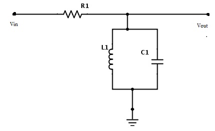
The centre frequency of the band pass filter which is also termed as ‘resonant peak’ can be formulated by using the below equation.
fc = 1/2π√(LC)
Where L = inductance of an inductor whose units are in Henry (H).
C = capacitance of a capacitor whose units are in Farad (F).
We can also design a band pass filter with inductors, but we know that due to high reactance of the capacitors the band pass filter design with RC elements is more advantage than RL circuits.
Frequency Response of Band Pass Filter
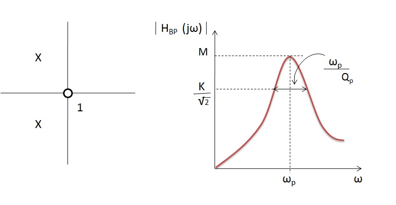
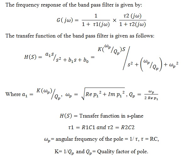
The pole frequency is approximately equals to the frequency of the maximum gain.
The frequency response curve of the band pass filter is as shown below: The ideal characteristics and the practical characteristics of the band pass filters are different because of the input reactance of the circuit.
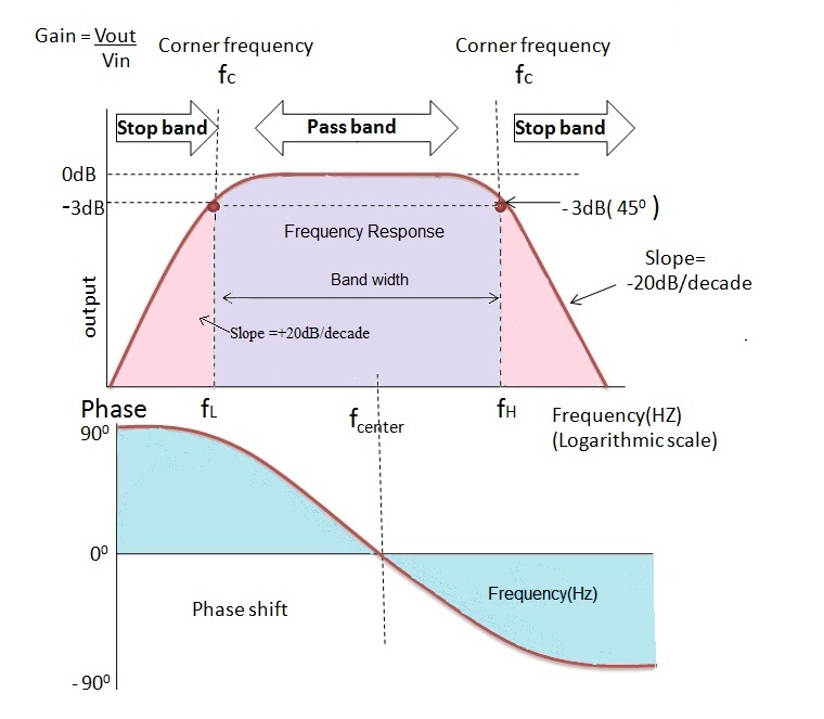
The gain of the input signal can be calculated by taking 20 log (Vout / Vin). The range can be quite large depending on inherent characteristics of the circuit. The signal is attenuated at low frequencies with the output increasing at a slope of +20 dB per decade or 6 dB per octave until the frequency reaches to lower cut off frequency ‘fL’.
At this frequency the gain of the signal reaches to the value 1/√2 = 70.7%.
After the cut-off frequency fL the output will increase with the increase of frequency with a rate of -20 dB per decade and attains maximum gain and this gain is constant until it reaches the higher cut off frequency ‘f_H’. After the higher cut-off frequency the output decreases at a slope of -20dB/decade or -6dB/octave.
Previously we have seen that the phase shift of first order filter is 90°. We know that the band pass filter is a second order filter so the phase shift is twice of the first order filter that is 180°. The phase angle will vary with the increase of the frequency. At centre frequency the output and input signals are in-phase with each other.
Below the resonant frequency the output signal leads the input signal and above the resonant frequency the output signal lags the input signal. The amplitude of the input signal is always greater than the output signal. In order to increase the gain of the circuit the resistance R1 value must be higher than the resistance R2.
Band Pass Filter Centre Frequency
The “Center frequency” or “Resonant frequency” at which the output gain is maximum can be obtained by calculating the Geometric mean of lower and upper cut-off frequencies.
fr2 = fH x fL
fr = √(fH x fL)
Where fr is the resonant frequency or centre frequency
fH – is the upper -3 dB cut-off frequency
fL – is the lower -3 dB cut-off frequency
Band Pass Filter Example
Let us assume that the band pass filter will allow the frequencies from 1 kHz to 30 kHz and it contains 10 kΩ resistor. By considering these values we can calculate the capacitance of the capacitor.
We already know that the cut off frequency value of the low pass filter must be higher than the high pass filter. So the cut off frequency of the high pass filter is 1 kHz and cut off frequency of the low pass filter is 30 kHz.
At High pass filter stage
fL = 1 kHz and Resistance R = 10 kΩ
C = 1/(2πfLR) = 1/(2*π*1000*1000) = 15.8 nF
At Low pass filter stage
fH = 30 kHz and Resistance R = 10 kΩ
C = 1/(2πfHR) = 1/(2*π*30000*10000) = 510 pF
From the above calculations the capacitor value required for the high pass filter is 15.8 nF and the low pass filter capacitor value is 510 pF.
Passive Band Pass Filter Summary
The band pass filter is obtained by cascading a low pass and high pass filter. It is a second order filter since it contains two reactive elements. The order of the filter depends on the number of cascading circuits using in the circuit.
The gain of the output signal is always less than the input signal.At the centre frequency the output signal is in-phase, but below centre frequency the output signal leads the phase with shift of +90° and above centre frequency the output signal will lag in phase with the phase shift of -90°.
The practical characteristics of the band pass filter are a bit different with respect to the ideal characteristics. This variation is mainly due to cascading of high pass filter with low pass filter.
The output gain is always less than unity. When we provide electrical isolation between the high pass and low pass filters we can attain better performance of the filter.
The band pass filter will optimize the sensitivity of the receiver. The high pass filter is first added to the design later low pass filter is added. Even though if we add a low pass filter first and then the high pass filter it will never make changes in the output signal.
The quality factor of the filter will depend upon the resistor value R1. If R1 is low the quality factor is low and if the R1 value is high then, the quality factor is high.
Applications of Band Pass Filter
- These are used in wireless communication medium at transmitter and receiver circuits. In transmitter section this filter will pass the only required signals and reduces the interfering of signals with other stations. In receiver section, it will help from unwanted signal penetration in to the channels.
- These are used to optimize the signal to noise ratio of the receiver.
- These are used in optical communication area like LIDARS.
- They are used in some of the techniques of colour filtering.
- These are also used in medical field instruments like EEG.
- In telephonic applications, at DSL to split phone and broad band signals.
The post Passive Band Pass RC Filter appeared first on Electronics Hub.
0 Comments