In this tutorial we will learn about Brushless Motors also known as Brushless DC Motors or BLDC Motors. We will see what is a BLDC Motor, its working principle, how to properly drive a Brushless DC Motor and also few applications.
Introduction
Brushless DC Motors or BLDC Motors have become a significant contributor of the modern drive technology. Their rapid gain in popularity has seen an increasing range of applications in the fields of Consumer Appliances, Automotive Industry, Industrial Automation, Chemical and Medical, Aerospace and Instrumentation.
Even though they have been used for drives and power generation for a long time, the sub kilowatt range, which has been dominated by Brushed DC Motors, has always been a grey area. But the modern power electronics and microprocessor technology has allowed the small Brushless DC Motors to thrive, both in terms price and performance.
What is a BLDC Motor?
A Brushless DC Motor is similar to a Brushed DC Motor but as the name suggests, a BLDC doesn’t use brushes for commutation but rather they are electronically commutated. In conventional Brushed DC Motors, the brushes are used to transmit the power to the rotor as they turn in a fixed magnetic field.
As mentioned earlier, a BLDC motor used electronic commutation and thus eliminates the mechanically torn brushes.
Construction of BLDC Motor
The main design difference between a brushed and brushless motors is the replacement of mechanical commutator with an electric switch circuit. Keeping that in mind, a BLDC Motor is a type of synchronous motor in the sense that the magnetic field generated by the stator and the rotor revolve at the same frequency.
Brushless Motors are available in three configurations: single phase, two phase and three phase. Out of these, the three phase BLDC is the most common one.
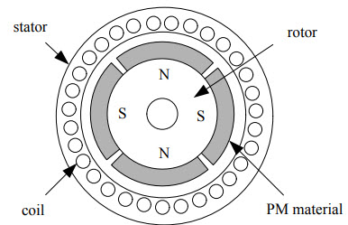
The following image shows the cross-section of a BLDC Motor.
As you can see in the image, a BLDC Motor consists of two main parts: a stator and a rotor.
Stator
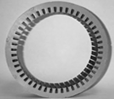
The structure of the stator of a BLDC Motor is similar to that of an induction motor. It is made up of stacked steel laminations with axially cut slots for winding. The winding in BLDC are slightly different than that of the traditional induction motor.
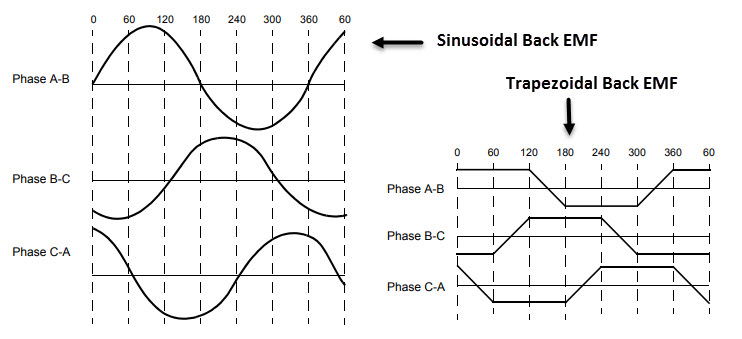
Generally, most BLDC motors consists of three stator windings that are connected in star or ‘Y’ fashion (without a neutral point). Additionally, based on the coil interconnections, the stator windings are further divided into Trapezoidal and Sinusoidal Motors.
In a trapezoidal motor, both the drive current and the back EMF are in the shape of a trapezoid (sinusoidal shape in case of sinusoidal motors). Usually, 48 V (or less) rated motors are used in automotive and robotics (hybrid cars and robotic arms).
Rotor
The rotor part of the BLDC Motor is made up of permanent magnets (usually, rare earth alloy magnets like Neodymium (Nd), Samarium Cobalt (SmCo) and alloy of Neodymium, Ferrite and Boron (NdFeB)).
Based on the application, the number of poles can vary between two and eight with North (N) and South (S) poles placed alternately. The following image shows three different arrangements of the poles. In the first case, the magnets are placed on the outer periphery of the rotor.
The second configuration is called magnetic-embedded rotor, where rectangular permanent magnets are embedded into the core of the rotor. In the third case, the magnets are inserted into the iron core of the rotor.
Position Sensors (Hall Sensors)
Since there are no brushes in a BLDC Motor, the commutation is controlled electronically. In order to rotate the motor, the windings of the stator must be energized in a sequence and the position of the rotor (i.e. the North and South poles of the rotor) must be known to precisely energize a particular set of stator windings.
A Position Sensor, which is usually a Hall Sensor (that works on the principle of Hall Effect) is generally used to detect the position of the rotor and transform it into an electrical signal. Most BLDC Motors use three Hall Sensors that are embedded into the stator to sense the rotor’s position.
The output of the Hall Sensor will be either HIGH or LOW depending on whether the North or South pole of the rotor passes near it. By combining the results from the three sensors, the exact sequence of energizing can be determined.
Read about HOW TO USE HALL EFFECT SENSOR WITH ARDUINO?
Working Principle
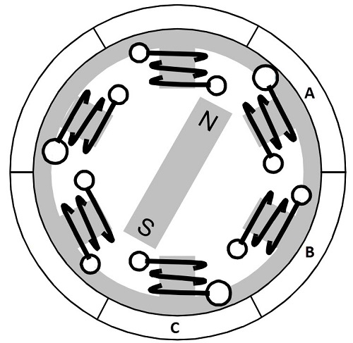
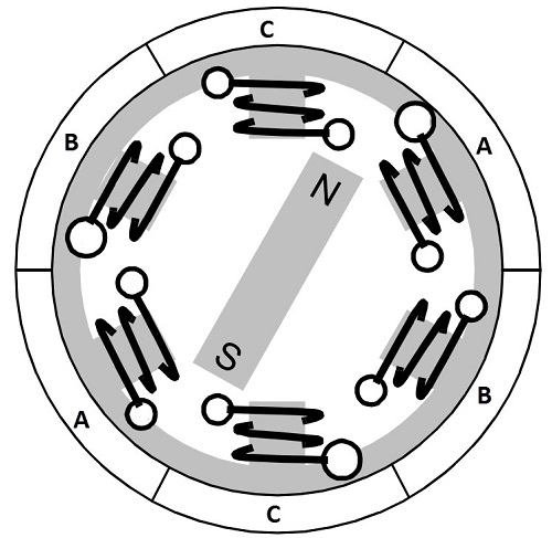
Consider the following setup of three windings in the stator designated A, B and C. For the sake of understanding, let us replace the rotor with a single magnet.
We know that when a current is applied through a coil, a magnetic field is generated and the orientation of the field lines i.e. the poles of the generated magnet will depend on the direction of the current flowing through the coil.
Using this principle, if we supply current to the coil A so that it will generate a magnetic field and attract the rotor magnet. The position of the rotor magnet will shift slightly clockwise and will align with A.
If we now pass current through coils B and C one after the other (in that order), the rotor magnet will rotate in clock wise direction.
To increase efficiency, we can wind the opposite coils using a single coil so that we get double attraction. Further increasing the efficiency, we can energize two coils at the same time so that one coil will attract the magnet and the other coil will repel it. During this time, the third will be idle.
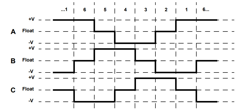
For a complete 3600 rotation of the rotor magnet, six possible combinations of the coils A, B and C are applicable and are shown in the following timing diagram.
Base on the above diagram, we can confirm that at any time, one phase is positive, one phase is negative and the third phase is idle (or floating). So, based on the inputs from the Hall Sensors, we have two switch the phases as per the above diagram.
Driving Brushless DC Motors
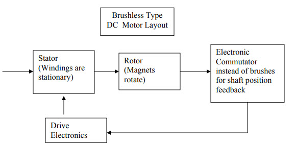
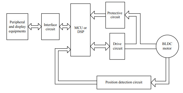
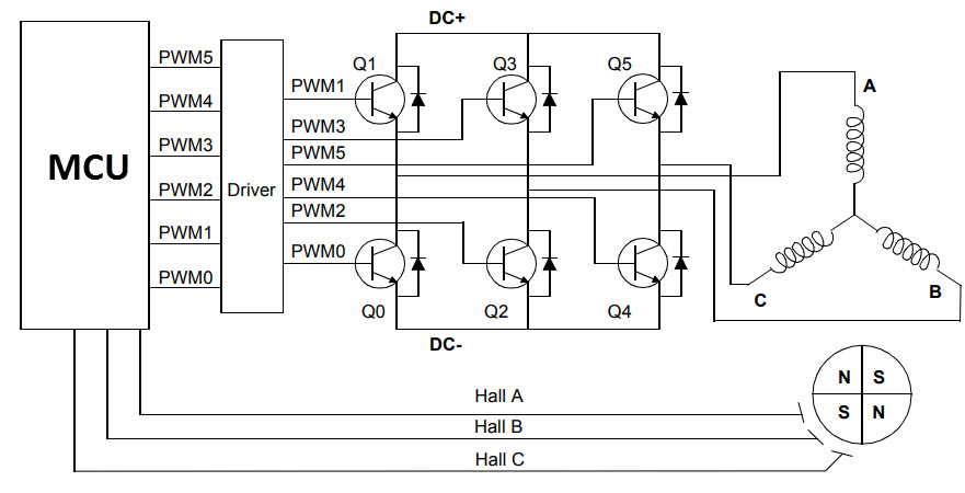
If stator and rotor are essential parts of a BLDC Motor that are integral to it, then the driving electronics are equally essential. Block diagram of a typical Brushless DC Motor control or drive system is shown in the following image.
This drive circuitry is often known as Electronic Speed Controller System or simply an ESC. One common setup is called the Full Bridge Drive Circuit. It consists of an MCU with PWM outputs, six MOSFETS for the three phases of the stator windings, feedback from the Hall sensors and some power supply related components.
The MCU can be programmed to appropriately switch the MOSFETS based on the data from the Hall Sensors.
Advantages of BLDC Motors
Since BLDC Motors are electronically commutated, there are several advantages over traditional Brushed DC Motors. Some of them are:
- No wear and tear (due to absence of brushes)
- High efficiency
- Better speed vs torque characteristics
- Long life
- Less noise or noiseless operation
- Significantly higher RPM
Applications of Brushless DC Motors
Some of the areas of applications of BLDC Motors are mentioned below:
- Single speed applications
- Adjustable speed applications
- Position control
- Low noise applications
- High speed applications
The post Introduction to Brushless DC Motors (BLDC Motor) appeared first on Electronics Hub.

0 Comments