In this tutorial, we will learn about Summing Amplifier, its configurations, types of summing amplifiers (inverting and non-inverting) and a few applications of Summing Amplifier.
One of the important application of an Operational Amplifier is the Summing Amplifier or otherwise known as Adder. As the name suggests, a Summing Amplifier is an Op-amp based circuit where multiple input signals of different voltages are added.
For information on the basics of Op-amp, read “Operational Amplifier Basics“.
Introduction
Many applications in electronic circuits require two or more analog signals to be added or combined into a single output. The summing amplifier does the exact same thing.
For this reason, summing amplifier is also called as Voltage adder since its output is the addition of voltages present at its input terminal.
The summing amplifier uses an inverting amplifier configuration, i.e. the input is applied to the inverting input terminal of the op-amp, while the non-inverting input terminal is connected to ground.
Due to this configuration, the output of voltage adder is out of phase with respect to the input by 180o.
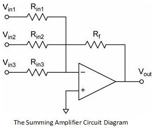
The circuit diagram of a summing amplifier is as shown in the figure above. The inverting amplifier circuit has only one voltage at the inverting input terminal. If more input voltages are connected to the inverting input terminal as shown, the resulting output will be the sum of all the input voltages applied, but inverted.
A circuit like this amplifies each input signal. The gain for each input is given by the ratio of the feedback resistor Rf to the input resistance in the respective branch.
For example,
Avin1(CL) = – (Rf/R1) and Avin2(CL) = – (Rf/R2)
Summing Amplifier Output Voltage Calculation
It is already been said that a summing amplifier is an inverting amplifier with more than one voltage at the input terminal. For an inverting amplifier, the output voltage is given as,
VOUT = – (Rf/RIN) VIN
So for the summing amplifier shown above, the output equation would be,
VOUT = – {(Rf/RIN1) VIN1 + (Rf/RIN2) VIN2 + (Rf/RIN3) VIN3}
In a summing amplifier, if the input resistances are not equal, the circuit is called a Scaling Summing Amplifier.
If all the input resistances are chosen to be of equal magnitude (Rin), then the output equation of the summing amplifier can be rewritten as,
VOUT = – {(Rf/RIN) {VIN1 + VIN2 + VIN3}
In general, a summing amplifier output equation is given as,
VOUT = – {(Rf/RIN) {V1 + V2 + V3 + ……….. + VN}
Sometimes, it is necessary to just add the input voltages without amplifying them. In such situations, the value of input resistance Rin1, Rin2, Rin3, etc. must be chosen equal to that of the feedback resistor Rf. Then, the gain of the amplifier will be unity. Hence the output voltage will be an addition of the input voltages.
Theoretically, one can apply as many input voltages to the input of the summing amplifier as is required. However, it must be noted that all of the input currents are added and then fed back through the resistor Rf, so one should also be aware of the power rating of resistors.
Non-Inverting Summing Amplifier
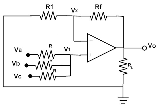
A non-inverting summing amplifier can also be constructed, using the non-inverting amplifier configuration. That is, the input voltages are applied to the non-inverting input terminal and a part of the output is fed back to the inverting input terminal, through voltage-divider-bias feedback.
A non-inverting summing circuit is shown in the figure below.
If the input resistances are equal, the output equation of the above circuit is given as,
V0 = Va + Vb + Vc
Design of non-inverting summing circuit is approached by first designing the non-inverting amplifier to have the required voltage gain. Then the input resistors are selected as large as possible to suit the type of the op-amp used.
Voltage Adder Example
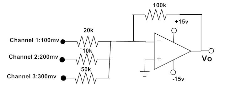
Three audio signals drive a summing amplifier as shown in the figure below. What is the output voltage?
The closed loop voltage gains of each channel can be calculated as,
ACL1 = – (Rf / R1) = – (100kΩ / 20kΩ) => ACL1 = -5
ACL2 = – (Rf / R2) = – (100kΩ / 10kΩ) => ACL2 = -10
ACL3 = – (Rf / R3) = – (100kΩ / 50kΩ) => ACL3 = -2
The output voltage of the summing amplifier is given as,
VOUT = – (ACL1 V1 + ACL2 V2 + ACL3 V3)
= – [(5x 100mV) + (10x200mV) + (2x300mV)]
= – (0.5 V + 2 V + 0.6 V)
VOUT = – 3.1 V
Summing Amplifier Applications
Audio Mixer
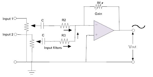
A summing amplifier is a useful circuit when two or more signals need be added or combined, like in audio mixing applications. The sounds from different musical instruments can be converted to a specific voltage level, using transducers, and connected as input to a summing amplifier.
These different signal sources will be combined together by the summing amplifier, and the combined signal is sent to an audio amplifier. An example circuit diagram of a summing amplifier as audio mixer is shown in the figure below.
The summing amplifier can function as a multi-channel audio mixer for several audio channels. No interference (feedback from one channel to the input of another channel) will occur because each signal is applied through a resistor, with its other end connected to ground terminal.
Digital to Analogue Converter (DAC)
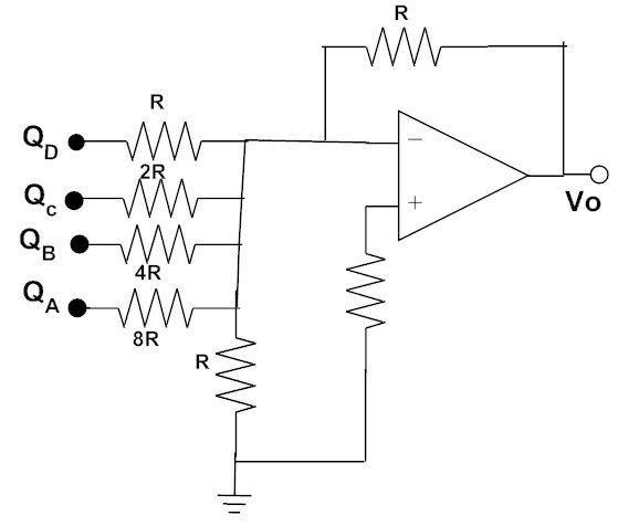
A digital to analogue converter converts the binary data applied to its input into an equivalent analogue voltage value. Real-time industrial control applications often use microcomputers. These microcomputers output digital data needs to be converted to an analogue voltage to drive the motors, relays, actuators, etc.
The simplest digital to analogue converter circuit uses a summing amplifier and a weighted resistor network. A typical 4-bit DAC circuit using a summing amplifier is shown in the below figure.
The inputs to the above shown summing amplifier are the binary data QA, QB, QC and QD, which are usually 5 V to represent logic 1 and 0 V to represent logic 0.
If the input resistors in each branch are chosen, such that the value of each input resistor is double the value of the resistor in previous input branch, then a digital logical voltage at the input will produce an output which is a weighted sum of the input voltages applied.
The accuracy of such a digital to analogue converter circuit is limited by the accuracy of the resistor values employed and the variations in representing the logic levels.
Previous Post – Non Inverting Op-Amp
Next Post – Differential Amplifier
The post Summing Amplifier appeared first on Electronics Hub.
0 Comments