Introduction
A non-inverting amplifier is an op-amp circuit configuration which produces an amplified output signal. This output signal of non-inverting op amp is in-phase with the input signal applied.
In other words a non-inverting amplifier behaves like a voltage follower circuit. A non-inverting amplifier also uses negative feedback connection, but instead of feeding the entire output signal to the input, only a part of the output signal voltage is fed back as input to the inverting input terminal of the op-amp.
The high input impedance and low output impedance of the non-inverting amplifier makes the circuit ideal for impedance buffering applications.
Ideal Non-Inverting Amplifier Circuit
The circuit diagram of an ideal non-inverting amplifier is as shown in the figure below.
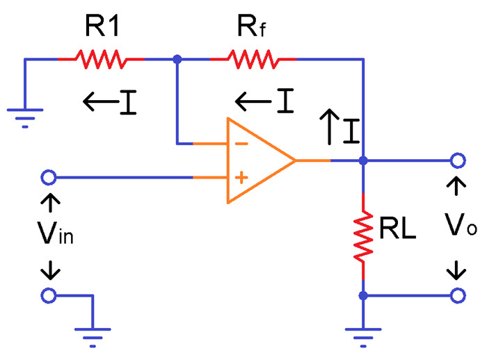
From the circuit, it can be seen that the output voltage is potentially divided across resistors R1 (R1 in the above picture) and R2 (Rf in the above picture), before it is applied to the inverting input.
When the non-inverting input is connected to ground, i.e. VIN = 0, the voltage at the inverting input terminal must also be at ground level; if not, any voltage difference between the input terminals would be amplified to move the inverting input terminal back to ground level, because of the concept of virtual ground.
Since the inverting input terminal is at ground level, the junction of the resistors R1 and R2 must also be at ground level. This implies that the voltage drop across R2 will be zero. As a result, the current flowing through R1 and R2 must be zero. Thus, there is zero voltage drops across R1, and therefore the output voltage is equal to the input voltage, which is 0V.
When a positive-going input signal is applied to the non-inverting input terminal, the output voltage will shift to keep the inverting input terminal equal to that of the input voltage applied. Hence, there will be a feedback voltage developed across resistor R2,
VR2 = VIN = I2R2
Where, I2 is the current flowing at the junction of resistors R1 and R2
VOUT = I2 (R1 + R2)
Voltage Gain of Non-Inverting Operational Amplifier
From the above equations of VIN and VOUT, the closed-loop voltage gain of the non-inverting amplifier can be calculated as
ACL = VOUT / VIN
= I2 (R1 + R2) / I2R2
= (R1 + R2) / R2
ACL = 1 + (R1 / R2)
The above gain equation is positive, indicating that the output will be in-phase with the applied input signal. The closed-loop voltage gain of a non-inverting amplifier is determined by the ratio of the resistors R1 and R2 used in the circuit.
Practically non-inverting amplifiers will have a resistor in series with the input voltage source, to keep the input current same at both input terminals.
Virtual Short
In a non-inverting amplifier, there exists a virtual short between the two input terminals. A virtual short is a short circuit for voltage, but an open-circuit for current. The virtual short uses two properties of an ideal op-amp:
- Since Rin is infinite, the input current at both the terminals is zero.
- Since AOL is infinite, the difference voltage (V1-V2) is always zero.
Although virtual short is an ideal approximation, it gives accurate values when used with heavy negative feedback. As long as the op-amp is operating in the linear region (not saturated, positively or negatively), the open loop voltage gain approaches infinity and a virtual short exists between two input terminals.
Because of the virtual short, the inverting input voltage follows the non-inverting input voltage. If the non-inverting input voltage increases or decreases, the inverting input voltage immediately increases or decreases to the same value. This action is often referred to as “Bootstrapping”.
Input Impedance of Non-Inverting Amplifier
The input impedance of an operational amplifier circuit is given as
ZIN = (1 + AOL β) Zi
Where, AOL = open-loop gain of op-amp
Zi = input impedance of op-amp without any feedback
β = feedback factor
For a non-inverting amplifier, the feedback factor is given as
β = R2 / (R1 + R2)
β = 1/ACL
Therefore, for a non-inverting amplifier circuit, the input impedance is given by the equation,
ZIN = {1 + (AOL / ACL)}Zi
Output Impedance of Non-Inverting Amplifier
The output impedance of an op-amp is expressed as,
ZOUT = ZO / (1+ AOL β)
Since, β = 1/ACL for a non-inverting amplifier the impedance is given as,
ZOUT = Z0 / {1 + (AOL / ACL)}
Voltage Follower Circuit
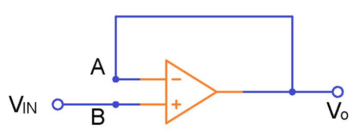
Voltage follower is one of the simplest uses of an operational amplifier, where the output voltage is exactly same as the input voltage applied to the circuit. In other words, the gain of a voltage follower circuit is unity.
The output of the op-amp is directly connected to the inverting input terminal, and the input voltage is applied to the non-inverting input terminal. The voltage follower, like a non-inverting amplifier, has very high input impedance and very low output impedance. The circuit diagram of a voltage follower is shown in the figure below.
It can be seen that the above configuration is same as the non-inverting amplifier circuit, with an exception that there are no resistors used. The gain of a non-inverting amplifier is given as,
ACL = 1 + (R1 / R2)
In the voltage follower, the resistor R1 is equal to zero and R2 is infinite. So the gain of the voltage follower will be equal to 1. A Voltage follower is also commonly known as a Unity Gain Buffer. The voltage follower or unity gain buffer circuit is commonly used to isolate different circuits, i.e. to separate one stage of circuit from another and also used in impedance matching applications.
In practice, the output voltage of a voltage follower will not be exactly equal to the input voltage applied and there will be a slight difference. This difference is due to the high internal voltage gain of the op-amp.
Note:
The open-loop voltage gain of an op-amp is infinite and the closed-loop voltage gain of the voltage follower is unity. This implies that by carefully selecting feedback components, we can accurately control the gain of a non-inverting amplifier.
Non-Inverting Amplifier Example
For the non-inverting amplifier shown in the figure below, calculate
i) The gain of the amplifier, ACL
ii) The output voltage, VO
iii) The current through the load resistor, IL.
iv) The output current, IO.
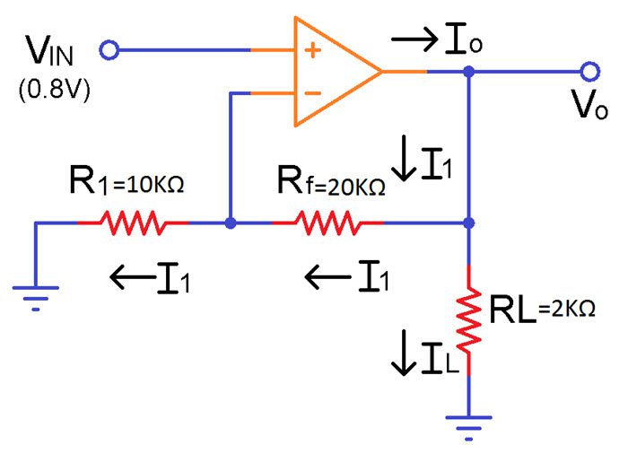
A) The potential at node B is Vin and because of the virtual short,
VA = VB = Vin = 0.8 V
The current I1 is given as,
I1 = VA/R1 = 0.8/10kΩ
I1 = 80µA
Since the op-amp input current is zero, the same I1 must flow through the resistor Rf.
i) The gain of the non-inverting amplifier,
ACL = 1 + (Rf/R1) = 1 + (20kΩ/10kΩ)
ACL = 3
ii) The output voltage,
VO = ACL. VIN = 3 (0.8V)
VO = 2.4 V
iii) Current through the load resistor,
IL = VO / RL = 2.4 / (2 x 10³Ω)
IL = 1.2 mA
iv) The output current,
IO = I1 + IL (KCL)
IO = 80µA + 1.2 mA
IO = 1.28mA
Non-Inverting Amplifier Summary
- A non-inverting amplifier uses a voltage-divider-bias negative feedback connection.
- The voltage gain is always greater than one.
- The voltage gain is positive, indicating that for AC input, the output is in-phase with the input signal and for dc input the output polarity is same as the input polarity.
- The voltage gain of non-inverting op-amp depends only on the resistor values, and is independent of the open-loop gain of the op-amp.
- The desired voltage gain can be obtained by choosing the appropriate values of the resistors.
The post Non Inverting Operational Amplifiers appeared first on Electronics Hub.


0 Comments